Posts

CUSTOM LAYOUT DESIGN (VLSI Custom Layout Design)

Image
Custom Layout: Layout Design starts normally with a schematic of the circuit layout and includes custom layout the use of EDA gear. It is the back-end pastime of trendy cells/Analog IP which involves layout design of transistor-stage circuits. As we all recognize, the again-quit layout of layout implementation known as an integrated circuit (IC) format -- is simplistically divided into ASIC-fashion float and full-custom go with the flow. This article will try to help customers define the numerous flavors of the whole-custom layout. The ideas offered here observe in popular. However, the examples and references proven refer in most cases to CMOS layout design. For a newcomer to VLSI layout, complete-custom go with the flowing manner polygon-degree format accomplished absolutely through the usage of easy polygon pusher software. A lot of people around the world carry out this feature and not unusual understanding says the only solution to increasing the quantity and veloc

"Physical Design"

Image
"Physical Design" The physical layout is the procedure of remodeling a circuit description into the physical layout, which describes the placement of cells and routes for the interconnections among them. ASIC Physical Design Flow : The main steps in the ASIC  physical design flow are: Design Netlist (after synthesis) Floorplanning Partitioning Placement Clock-tree Synthesis (CTS) Routing Physical Verification GDS II Generation The physical layout is primarily based on a netlist that is the stop result of the Synthesis procedure. Synthesis converts the RTL layout normally coded in VHDL or Verilog HDL to gate-stage descriptions which the subsequent set of gear can study/understand. This netlist carries statistics at the cells used, their interconnections, the location used, and different information. Typical synthesis gear are Cadence RTL Compiler/Build Gates/Physically Knowledgeable Synthesis (PKS) Synopsys Design Compiler During the synthes

"Digital Logic Gates"

Image
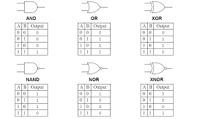
Digital Logic Gates A Digital Logic Gate is a digital circuit which makes logical selections based at the mixture of virtual signals gift on its inputs. Gate logic is also called as restoring logic. This is a logic circuitry designed so that even with an imperfect input pulse a standard output occurs at the exit of each successive logic gate. Digital logic gates can have more than one input, for example, inputs A, B, C, D, etc., but generally, only have one digital output. Individual logic gates can be connected or cascaded together to form a logic gate function with any desired number of inputs, or to form combinational and sequential type circuits, or to produce different logic gate functions from standard gates. Digital Logic States The  Digital Logic Gate  is the basic building block from which all digital electronic circuits and microprocessor-based systems are constructed. Basic digital logic gates perform logical operations of  AND ,  OR  and  NOT  on binar

About "ICLabs"

Image
ICLabs is one of the best VLSI Training Center in Bangalore.  Which provide Both Backend, Frontend courses and also offers some other courses like Embedded design, PCB Layout, IoT, AI, ML.  Which was founded by Mr. Prasad Rallabandi in the year of 2017. He has 15+ years of experience in VLSI. Expert Trainers having 10+ years of industry experience in VSLI. 24 hrs lab facility. Hands-On training classes. 100% placement assurance.